Creating a DIY 433 MHz ESP8266-based Home Automation bridge to switch DIP remote control outlets

A couple of years ago I built a pretty basic smart home application allowing me to control my remote controlled sockets via an Android app or a Web Extension. It’s based on the rcswitch library run on an Apache. The 433 MHz signals are sent by a FS1000A transmitter hooked up via GPIO to a Raspberry Pi. The whole setup lied on the ground in a corner of my apartment behind a curtain next to my network wall jack. Now where we have just moved to a nice new and twice as big home, I needed a solution which could be placed in the middle of all rooms to allow the rather weak 433 MHz signals to reach every receiver. Additionally, I wanted to get rid of having to maintain a full Ubuntu server, which only serves as a light switch for the most part.

Firefox WebExtension used to turn on desk lamp

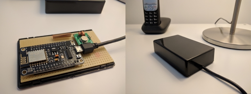
Around that time, I stumbled upon the ESP8266: a low-cost WiFi microchip with full TCP/IP stack and microcontroller capability – ideally soldered on a NodeMCU or Wemos D1 for the maximum level of convenience. Arduino and Wifi: a whole new world of IoT-possibilities. Once you’ve added the board manager to your Arduino IDE, you can use those tiny boards just like an ordinary Arduino. As the Arduino WebServer library can turn a NodeMCU development board into a light-weight HTTP server and the rcswitch library is also available on Arduino, I decided to put both – NodeMCU and FS1000A – into a junction box to create a DIY 433 MHz RF WiFi bridge.

To reach the bridge you should either assign a static IP or use mDNS. Keep in mind that mDNS is not supported by all operating systems out of the box. If in doubt, use a static IP.  To make the bridge accessible from outside your home network, you need to open and forward a port on your router (port 80 by default and can be changed in line 10). It’s recommend to secure any connection made through the public internet. By the time I was writing the script, there hasn’t been a HTTPS server implementation around. However, I found HelloServerBearSSL while writing this article. It looks very promising and is definitely worth a try.

433Mhz RF WiFi Bridge Junction Box opened and closed
433 MHz RF WiFi Bridge Junction Box opened and closed

This project works with simple DIP-switch remote outlets only. It became quite hard to get the “old” DIP outlets as most producers switched to the “new” outlets, which use a button on the receivers to “learn” a signal. There is a NewRemoteSwitch library to deal with them. But as I just recently found one last triple pack in a dollar store, I am stocked until I will eventually move to Wifi controlled outlets.

Enough talk. A typical request contains the five digit system code, five digit unit code and a binary power code separated by comma. You can also concatenate multiple commands using semicolon. A sample request to switch on outlet A and switch off outlet B would look like this:

x.x.x.x/switch?command=10010,00001,1;10010,0010,0

Here is the code. Further down is a download link.

#include <ESP8266mDNS.h>
#include <ESP8266WebServer.h>
#include <ESP8266WiFi.h>
#include <RCSwitch.h>
#include <WiFiClient.h>

const char* ssid = "SSID";
const char* password = "PASSWORD";

ESP8266WebServer server(80);
RCSwitch rcswitch = RCSwitch();


void setup(void) {

  Serial.begin(115200);

  digitalWrite(2, HIGH); // Turn onboard led off
  rcswitch.enableTransmit(15);

  WiFi.mode(WIFI_STA); //  (WIFI_AP) will spawn an access point. useful when no router is present.
  WiFi.begin(ssid, password);

  Serial.println("");

  if (WiFi.waitForConnectResult() != WL_CONNECTED) {

    Serial.println("Wifi connect failed! Rebooting...");
    delay(5000);
    ESP.restart();
  }

  MDNS.begin("bridge"); // will make the bridge available under bridge.local

  Serial.println("");
  Serial.print("Connected to ");
  Serial.println(ssid);
  Serial.print("IP address: ");
  Serial.println(WiFi.localIP());

  server.on("/switch", handleSwitchRequest); //Associate the handler function to the path

  server.begin();
  Serial.println("HTTP server started");
}


int countCharacterOccurrence(char *haystack, char needle) {

  int count = 0;

  for (int i = 0; i < strlen(haystack); i++)

    if (haystack[i] == needle) {

      count++;
    }

  return count;
}


void handleSwitchRequest() {

  bool isBadRequest = false;
  String response = "";

  if (server.arg("command") != "") {

    char commands[1024]; // make some room to get the string server args
    server.arg("command").toCharArray(commands, sizeof(commands)); // convert string to char array

    char *pointerCommands = commands; // create a pointer and store commands at its memory's address
    char *commandToken;
    char *subCommandToken; 

    while ((commandToken = strsep(&pointerCommands, ";")) != NULL) { // delimiter is the semicolon. we are using the address of the pointer to the input string. strsep expects the address (pointer) of a pointer to the string that should be separated. if found, pointerCommands is updated to point past the delimiter. returns a pointer to the result token.

      int counter = 0;
      char* commandArray[3];

      if (countCharacterOccurrence(commandToken, ',') != 2) {

        isBadRequest = true;
        response += "ERROR:\t" + String(commandToken) + " - Bad format. Expected: ?command=10000,10000,1;\n";
        continue;
      }

      while ((subCommandToken = strsep(&commandToken, ",")) != NULL) { // delimiter is the comma

        commandArray[counter++] = subCommandToken;
      }

      if (strcmp(commandArray[2], "1") == 0) {

        rcswitch.switchOn(commandArray[0], commandArray[1]);
        response += "ON:\t" + String(commandArray[0]) + "," + String(commandArray[1]) + "," + String(commandArray[2]) + "\n";

      } else if (strcmp(commandArray[2], "0") == 0) {

        rcswitch.switchOff(commandArray[0], commandArray[1]);
        response += "OFF:\t" + String(commandArray[0]) + "," + String(commandArray[1]) + "," + String(commandArray[2]) + "\n";

      } else {

        isBadRequest = true;
        response += "ERROR:\t" + String(commandArray[0]) + "," + String(commandArray[1]) + "," + String(commandArray[2]) + " - Power must be either 1 or 0.\n";
      }

      delay(50); // will otherwise hick up and fatal
    }
  }

  server.send(isBadRequest ? 400 : 200, "text / plain", response);
}


void loop(void) {

  server.handleClient();
}

DOWNLOAD: 433MHzWifiBridge Project


Using a ML8511 UV sensor and an Arduino Nano to test UV-filtering properties of sunglasses

Do cheap freebie sunglasses really block UV light or are they mostly just toys, which pose a serious health risk to your eyes? That’s the question I asked myself when coming across one of my wife’s cheesy glasses. I always warned her, but never could proof the potential risk of increased UV exposure caused by non-blocking tinted glasses. Until now…

After buying one of those cheap Arduino Nano clones (oh the irony), I started experimenting with all kind of sensors. One of them was the ML8511. This sensor detects 280 – 390 nm light most effectively. This wavelength is categorized as part of the UVB spectrum and most of the UVA spectrum. Overexposure to UVA radiation has been linked to the development of certain types of cataracts, and research suggests UVA rays may play a role in development of macular degeneration.

The setup was straight forward: I hung an UV LED torch over the sensor using my helping hand. The emitted 395 nm light is slightly out of range, but the torch has proven to be a reliable source of detectable UV light. Pointing the beam directly at the photo resistor was crucial as the amount of measurable UV light decreases rapidly on the beam’s edges. I used a sketch from Sparkfun to read the sensor’s output. The unit measure wasn’t really necessary as I was mainly interested in the relative amount of absorbed UV light. But having the Milliwatts per square Centimeter came in handy. The problem was that the script outputted -1 mW/cm² when being in an UV-free environment. The solution was unexpected: The voltage of the “supposed to be 1% accurate” 3v3 Nano output was in fact only 10% accurate and came out as being 3.61 volts. Seems like testing cheap sunglasses using even cheaper tools isn’t the best idea. However, the sketch’s output can be calibrated by adjusting the hard-coded reference variable in the script to the actual reference voltage.

All tested sunglasses absorbed a fair amount of UV light. The best pairs filtered the UV light nearly completely (meaning below a level that can be detected by an ML8511 in this particular setup and ignoring the minor UV halo around the frame due to the sensor not being fully covered by the glass). The rest ranged between letting 1 – 10% of UV irradiation to pass through – proving that all sunglasses had UV-filtering properties. Given that a good UV protection can be bought for less than 10 Euros (the best pair tested), it is probably a good idea to not use freebie sunglasses if you have a bad gut feeling. As general advice, make sure that you buy your glasses from trusted retailers (optician, pharmacy, supermarket, etc.) or let them be tested.

Seeing is believing. 😉


UV test setup with ML8511 and Arduino Nano R3
Serial monitor output of the sketch used


 /* 
 ML8511 UV Sensor Read Example
 By: Nathan Seidle
 SparkFun Electronics
 Date: January 15th, 2014
 License: This code is public domain but you buy me a beer if you use this and we meet someday (Beerware license).

 The ML8511 UV Sensor outputs an analog signal in relation to the amount of UV light it detects.

 Connect the following ML8511 breakout board to Arduino:
 3.3V = 3.3V
 OUT = A0
 GND = GND
 EN = 3.3V
 3.3V = A1
 These last two connections are a little different. Connect the EN pin on the breakout to 3.3V on the breakout.
 This will enable the output. Also connect the 3.3V pin of the breakout to Arduino pin 1.

 This example uses a neat trick. Analog to digital conversions rely completely on VCC. We assume
 this is 5V but if the board is powered from USB this may be as high as 5.25V or as low as 4.75V:
 http://en.wikipedia.org/wiki/USB#Power Because of this unknown window it makes the ADC fairly inaccurate
 in most cases. To fix this, we use the very accurate onboard 3.3V reference (accurate within 1%). So by doing an
 ADC on the 3.3V pin (A1) and then comparing this against the reading from the sensor we can extrapolate
 a true-to-life reading no matter what VIN is (as long as it's above 3.4V).

 Test your sensor by shining daylight or a UV LED: https://www.sparkfun.com/products/8662

 This sensor detects 280-390nm light most effectively. This is categorized as part of the UVB (burning rays)
 spectrum and most of the UVA (tanning rays) spectrum.

 There's lots of good UV radiation reading out there:
 http://www.ccohs.ca/oshanswers/phys_agents/ultravioletradiation.html
 https://www.iuva.org/uv-faqs

*/

//Hardware pin definitions
int UVOUT = A0; //Output from the sensor
int REF_3V3 = A1; //3.3V power on the Arduino board

void setup()
{
  Serial.begin(9600);

  pinMode(UVOUT, INPUT);
  pinMode(REF_3V3, INPUT);

  Serial.println("ML8511 example");
}

void loop()
{
  int uvLevel = averageAnalogRead(UVOUT);
  int refLevel = averageAnalogRead(REF_3V3);

  //Use the 3.3V power pin as a reference to get a very accurate output value from sensor
  float outputVoltage = 3.3 / refLevel * uvLevel;   // adjust outputVoltage to actual voltage in case you read negative values.

  float uvIntensity = mapfloat(outputVoltage, 0.99, 2.8, 0.0, 15.0); //Convert the voltage to a UV intensity level

  Serial.print("output: ");
  Serial.print(refLevel);

  Serial.print("ML8511 output: ");
  Serial.print(uvLevel);

  Serial.print(" / ML8511 voltage: ");
  Serial.print(outputVoltage);

  Serial.print(" / UV Intensity (mW/cm^2): ");
  Serial.print(uvIntensity);

  Serial.println();

  delay(100);
}

//Takes an average of readings on a given pin
//Returns the average
int averageAnalogRead(int pinToRead)
{
  byte numberOfReadings = 8;
  unsigned int runningValue = 0; 

  for(int x = 0 ; x < numberOfReadings ; x++)
    runningValue += analogRead(pinToRead);
  runningValue /= numberOfReadings;

  return(runningValue);  
}

//The Arduino Map function but for floats
//From: http://forum.arduino.cc/index.php?topic=3922.0
float mapfloat(float x, float in_min, float in_max, float out_min, float out_max)
{
  return (x - in_min) * (out_max - out_min) / (in_max - in_min) + out_min;

}


Reference and further reading:

https://learn.sparkfun.com/tutorials/ml8511-uv-sensor-hookup-guide
https://en.wikipedia.org/wiki/Ultraviolet
http://www.canadianjournalofophthalmology.ca/article/S0008-4182(17)30495-7/fulltext