Do cheap freebie sunglasses really block UV light or are they mostly just toys, which pose a serious health risk to your eyes? That’s the question I asked myself when coming across one of my wife’s cheesy glasses. I always warned her, but never could proof the potential risk of increased UV exposure caused by non-blocking tinted glasses. Until now…
After buying one of those cheap Arduino Nano clones (oh the irony), I started experimenting with all kind of sensors. One of them was the ML8511. This sensor detects 280 – 390 nm light most effectively. This wavelength is categorized as part of the UVB spectrum and most of the UVA spectrum. Overexposure to UVA radiation has been linked to the development of certain types of cataracts, and research suggests UVA rays may play a role in development of macular degeneration.
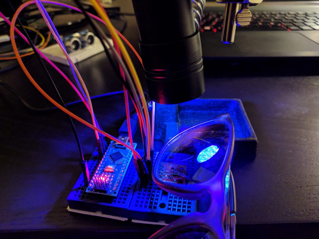
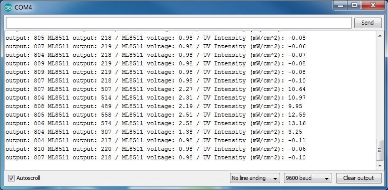
The setup was straight forward: I hung an UV LED torch over the sensor using my helping hand. The emitted 395 nm light is slightly out of range, but the torch has proven to be a reliable source of detectable UV light. Pointing the beam directly at the photo resistor was crucial as the amount of measurable UV light decreases rapidly on the beam’s edges. I used a sketch from Sparkfun to read the sensor’s output. The unit measure wasn’t really necessary as I was mainly interested in the relative amount of absorbed UV light. But having the Milliwatts per square Centimeter came in handy. The problem was that the script outputted -1 mW/cm² when being in an UV-free environment. The solution was unexpected: The voltage of the “supposed to be 1% accurate” 3v3 Nano output was in fact only 10% accurate and came out as being 3.61 volts. Seems like testing cheap sunglasses using even cheaper tools isn’t the best idea. However, the sketch’s output can be calibrated by adjusting the hard-coded reference variable in the script to the actual reference voltage.
All tested sunglasses absorbed a fair amount of UV light. The best pairs filtered the UV light nearly completely (meaning below a level that can be detected by an ML8511 in this particular setup and ignoring the minor UV halo around the frame due to the sensor not being fully covered by the glass). The rest ranged between letting 1 – 10% of UV irradiation to pass through – proving that all sunglasses had UV-filtering properties. Given that a good UV protection can be bought for less than 10 Euros (the best pair tested), it is probably a good idea to not use freebie sunglasses if you have a bad gut feeling. As general advice, make sure that you buy your glasses from trusted retailers (optician, pharmacy, supermarket, etc.) or let them be tested.
Seeing is believing. 😉


 /*
 ML8511 UV Sensor Read Example
 By: Nathan Seidle
 SparkFun Electronics
 Date: January 15th, 2014
 License: This code is public domain but you buy me a beer if you use this and we meet someday (Beerware license).

 The ML8511 UV Sensor outputs an analog signal in relation to the amount of UV light it detects.

 Connect the following ML8511 breakout board to Arduino:
 3.3V = 3.3V
 OUT = A0
 GND = GND
 EN = 3.3V
 3.3V = A1
 These last two connections are a little different. Connect the EN pin on the breakout to 3.3V on the breakout.
 This will enable the output. Also connect the 3.3V pin of the breakout to Arduino pin 1.

 This example uses a neat trick. Analog to digital conversions rely completely on VCC. We assume
 this is 5V but if the board is powered from USB this may be as high as 5.25V or as low as 4.75V:
 http://en.wikipedia.org/wiki/USB#Power Because of this unknown window it makes the ADC fairly inaccurate
 in most cases. To fix this, we use the very accurate onboard 3.3V reference (accurate within 1%). So by doing an
 ADC on the 3.3V pin (A1) and then comparing this against the reading from the sensor we can extrapolate
 a true-to-life reading no matter what VIN is (as long as it's above 3.4V).

 Test your sensor by shining daylight or a UV LED: https://www.sparkfun.com/products/8662

 This sensor detects 280-390nm light most effectively. This is categorized as part of the UVB (burning rays)
 spectrum and most of the UVA (tanning rays) spectrum.

 There's lots of good UV radiation reading out there:
 http://www.ccohs.ca/oshanswers/phys_agents/ultravioletradiation.html
 https://www.iuva.org/uv-faqs

*/

//Hardware pin definitions
int UVOUT = A0; //Output from the sensor
int REF_3V3 = A1; //3.3V power on the Arduino board

void setup()
{
  Serial.begin(9600);

  pinMode(UVOUT, INPUT);
  pinMode(REF_3V3, INPUT);

  Serial.println("ML8511 example");
}

void loop()
{
  int uvLevel = averageAnalogRead(UVOUT);
  int refLevel = averageAnalogRead(REF_3V3);

  //Use the 3.3V power pin as a reference to get a very accurate output value from sensor
  float outputVoltage = 3.3 / refLevel * uvLevel;   // adjust outputVoltage to actual voltage in case you read negative values.

  float uvIntensity = mapfloat(outputVoltage, 0.99, 2.8, 0.0, 15.0); //Convert the voltage to a UV intensity level

  Serial.print("output: ");
  Serial.print(refLevel);

  Serial.print("ML8511 output: ");
  Serial.print(uvLevel);

  Serial.print(" / ML8511 voltage: ");
  Serial.print(outputVoltage);

  Serial.print(" / UV Intensity (mW/cm^2): ");
  Serial.print(uvIntensity);

  Serial.println();

  delay(100);
}

//Takes an average of readings on a given pin
//Returns the average
int averageAnalogRead(int pinToRead)
{
  byte numberOfReadings = 8;
  unsigned int runningValue = 0;

  for(int x = 0 ; x < numberOfReadings ; x++)
    runningValue += analogRead(pinToRead);
  runningValue /= numberOfReadings;

  return(runningValue);
}

//The Arduino Map function but for floats
//From: http://forum.arduino.cc/index.php?topic=3922.0
float mapfloat(float x, float in_min, float in_max, float out_min, float out_max)
{
  return (x - in_min) * (out_max - out_min) / (in_max - in_min) + out_min;

}
Reference and further reading:
https://learn.sparkfun.com/tutorials/ml8511-uv-sensor-hookup-guide
https://en.wikipedia.org/wiki/Ultraviolet
http://www.canadianjournalofophthalmology.ca/article/S0008-4182(17)30495-7/fulltext
